

Exploring the Turing Machine
The Turing Machine is a cornerstone of computational theory, representing the foundation upon which modern computing is built. This abstract concept was revolutionary, laying the groundwork for the advanced systems we see today, especially in the field of robotics.
Named after the visionary mathematician Alan Turing, my introduction to his work came through the cinematic portrayal in "The Imitation Game." The film dramatizes Turing’s efforts to decrypt German communications during World War II, encapsulating the idea that "Only a machine could beat another machine."

At its core, the Turing Machine simulates the process of human calculation by recording inputs and transitioning through states. This pivotal concept highlights why the Turing Machine is often heralded as the precursor to the modern computer.
Delving into specifics, as outlined on the Turing Machine Wikipedia page, we define a Turing Machine using a 7-tuple: M = (Q, Σ, Γ, δ, q0, qaccept, qreject), where each element represents:
-
Q: a finite set of states -
Σ: the input alphabet (excluding the blank symbol ‘B’) -
Γ : the tape alphabet, satisfying:
- Σ ⊆ Γ (the input alphabet is a subset of the tape alphabet)
- B ∈ Γ (the blank symbol is included in the tape alphabet)
-
q0: the starting state, an element of Q -
qaccept: the accepting state, within Q -
qreject: the rejecting state, also within Q -
δ: the transition function, defined as δ : Q × Γ → Q × Γ × {L, R}
This structure is admittedly intricate. But what if our ambitions are more modest, aiming for a model that simply retains the current state and transitions based on the input?
Enter the Finite State Machine (FSM). It can be expressed more succinctly with a 5-tuple: M = (Q, Σ, δ, q0, F), which includes:
Q: a finite set of statesΣ: a finite set of input symbols, the alphabetδ: the transition function, δ : Q × Σ → Qq0: the initial state, from the set QF: the set of final or accepting states
Compared to the Turing Machine, the FSM lacks the infinite tape for recording input. It operates solely on the present input and state, making it an ideal model for robotic systems that need to swiftly react to environmental cues.
Comparison Diagram of Turing Machine and Finite State Machine
Below is a diagram illustrating the relationship and differences between the Turing Machine and the Finite State Machine:
This diagram clearly depicts the distinct roles and functionalities of the Turing Machine and Finite State Machine in computational theory and robotics.
Why Robots Need a Finite State Machine (FSM)
Robots are engineered to navigate and respond to the tangible realm around them, frequently tasked with executing complex sequences or reacting to diverse stimuli. A Finite State Machine (FSM) is an exemplary paradigm for orchestrating these activities and responses. It furnishes a transparent and organized framework that directs the robot through various operational states, culminating in consistent and controlled conduct.
Beyond the FSM, one might consider using a global variable to represent the current state of a robot. Upon receiving an input, this variable could be updated accordingly. However, this approach has its drawbacks, primarily in scalability and maintainability. As the complexity of tasks increases, relying on a single variable for state management becomes unwieldy and prone to error.
FSMs streamline this process by encapsulating the state information within a well-defined system. When an FSM processes an input, it evaluates the current state and the input itself to decide upon an output and the subsequent state. This decision-making is governed by the transition function, a core component of the FSM that acts as a set of rules or logic dictating how state transitions occur.
This mechanism allows for a modular approach where each state is isolated, and its behavior can be understood without needing to consider the entire system. The FSM can be designed to handle specific inputs differently depending on the current state, which is critical for robots that must adapt to a changing environment.
For instance, consider a robot vacuum cleaner that has states such as ‘Idle’, ‘Cleaning’, and ‘Charging’. If the battery level is low, regardless of whether it’s currently idle or cleaning, the FSM can dictate that the robot transition to the ‘Charging’ state. Similarly, if the robot finishes charging or the user presses the start button, the FSM can direct the robot to transition back to ‘Cleaning’ from the ‘Idle’ or ‘Charging’ states.
Hence, the FSM’s ability to judge and act based on both its current state and input not only provides precise control over the robot’s behavior but also isolates the conditions for transitions, making the system more robust and less prone to cascading failures. It’s the distinction between a robot that merely reacts and one that responds with discernment to its environment.
Designing the Protocol First
Before delving into the implementation of the Finite State Machine (FSM), it’s imperative to meticulously design the protocol. This process is akin to an architect meticulously drafting blueprints prior to the commencement of construction. We must delineate all conceivable states and their respective transitions. This preliminary step is vital to ensure a comprehensive and well-thought-out plan that encapsulates the robot’s intended functionalities and its responses to various events.
The Case of the AGV in the System
Let’s revisit our familiar subject – the Automated Guided Vehicle (AGV). In the system under consideration, it’s essential for the AGV to accurately gather information such as its position, state, status, power level, etc. The model for this data collection can be represented as follows:
template_agv_state = {
    "state": 0,
    "stateDuration": 123,
    "curCoord": {...},
    "locConfidence": 100,
    "curSiteID": 0,
    "curBatteryPct": 0,
    "speed": {...},
    "map": {...},
    "task": {...},
    "laden": {...},
    "action": {...},
    ...
}
As illustrated, the system retrieves this information from different layers within the robot by dispatching a variety of MQTT topics at varying frequencies. Each data piece has its unique trigger; for instance, the state information might be updated at about 2Hz, which is slightly lower than the 5Hz frequency of the sensor data. The action status is transmitted every time an action is completed or fails.
Consequently, the FSM disseminates these data using topics such as:
agv/heartbeat/{ID}
agv/state/{ID}
agv/status/{ID}
...
agv/motion/{ID}
...
The format adopted is:
{Sender}/{Topic}/{ID}The reason for placing the {ID} at the end is a matter of personal preference – I’m not fond of splitting the topic with a + symbol.
The content of the topic agv/heartbeat/{ID} is structured as follows:
{
    "agvid": "XXX",
    "timestamp": 1692861317.338879,
    "msg_type": "heartbeat",
    "data": {...}
}
This format allows the Dispatching system to verify the data source and determine the specific subtopic it belongs to.
Similarly, the Dispatching system sends commands using topics like dispatch/command/{ID}. There’s not much more to discuss in this regard.
System Structure and Workflow
The structure of this system is depicted in the following diagram:

The workflow of the system is illustrated here:
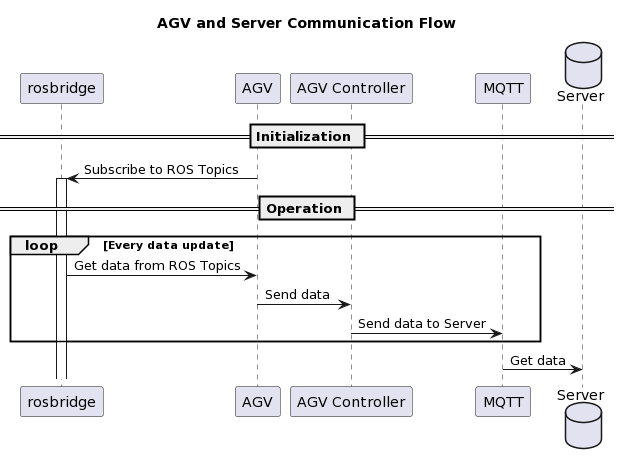
This refined approach to protocol design ensures that the AGV operates efficiently within the system, responding accurately to the commands and data it receives.
Enhancing State Transitions in FSM
In the realm of Finite State Machines (FSM), dynamism is key. Transitions between states aren’t just spontaneous; they’re driven by specific events or conditions. When crafting an FSM for a robot, it’s crucial to meticulously define the triggers for these state transitions. This precision is vital for averting unforeseen behaviors and ensuring robust control over the robot’s operational dynamics.
Designing AGV’s State Series
In alignment with the product requirements, I have conceptualized a series of states for the Automated Guided Vehicle (AGV), as depicted in the following state diagram:
This visual representation is instrumental in understanding the various states the AGV can assume and the transitions between them, ensuring a clear roadmap for its behavior under different scenarios.
Choosing Python for Development
For the development of this FSM, I have opted for Python. The rationale behind this choice is detailed in my recent presentation, which can be accessed here:
Read My Speech on Python Usage
Program Structure
The structure of the program, which underpins the FSM and its operations, is outlined in the following diagram:
This structural blueprint provides a comprehensive view of how the various components of the program interact, ensuring a cohesive and well-organized implementation of the FSM in the AGV system.
Navigating Through Fatal States in FSM
In the journey of a Finite State Machine (FSM), not every state leads towards the desired goal. Some states can be dead ends or ‘fatal’ states, where the system encounters errors or situations that disrupt normal operations. It’s crucial for an FSM, especially in complex systems like Automated Guided Vehicles (AGV), to have a mechanism to recover from these states. This capability is pivotal in ensuring the robot’s resilience and reliability.
The Concept of Backtracking
Backtracking from fatal states involves designing the FSM such that the robot can revert to a safe or neutral state. This process is akin to a reset, allowing the robot to recalibrate and resume normal operations. The design must include clear pathways from these fatal states to recovery states.
Implementing Recovery in AGV’s FSM
In the context of an AGV, consider a scenario where the robot encounters an unexpected obstacle or system error. The FSM should be able to recognize this as a ‘fatal state’ and initiate a series of actions to move the AGV back to a stable state. This could involve retracting steps, recalculating paths, or even shutting down certain functions temporarily.
State Diagram for Recovery
The following state diagram illustrates the process of navigating through and recovering from fatal states:
In this diagram, the AGV transitions from normal operation to a fatal state upon encountering an error. It then moves to a recovery state, where attempts are made to rectify the issue. If successful, the AGV returns to normal operation. However, if recovery fails, the system may need to shut down to prevent further complications.
Conclusion
The ability to backtrack from fatal states is not just a safety feature; it’s a testament to the robustness of the FSM design. It ensures that the AGV can handle uncertainties and continue to operate effectively, thereby enhancing its reliability in dynamic environments.
Through careful planning and strategic implementation, FSMs in robotic systems like AGVs can be equipped to handle challenges, ensuring smooth and uninterrupted operations.

发表回复